
The nameplate reads “230 V, 50/60 Hz.” However, the power supply at our test station only provides 50 Hz. How does the device behave at 60 Hz? Does a fan powered directly from the mains operate differently? Does the current draw change, or does an internal auxiliary voltage remain within the specified range? These questions cannot be answered based solely on the local power supply.
Let’s take as an example a properly authorized assembly whose behavior is to be compared at both frequencies. A transformer can adjust the voltage but does not change the power-line frequency. An adjustable AC source, on the other hand, provides the required AC voltage and frequency. This allows you to compare two defined supply conditions at the same test station without having to rely on a different power grid.
Change the frequency, keep the voltage the same
For the first comparison, the voltage remains at 230 V. One test run is conducted at 50 Hz, and a second at 60 Hz; the load and other test conditions are kept as consistent as possible. Only when a different, equally permissible voltage is to be examined is a separate comparison conducted for that voltage. This makes it easier to attribute any changes in current consumption or temperature to the correct cause.
DF-C Series AC power supplies allow you to adjust voltage and frequency independently. The variable range of 47 to 63 Hz covers both mains frequencies. The voltage regulation maintains the specified rms value within the specified limits. For this experiment, this means that you can vary the frequency as needed and use the desired supply voltage as a fixed reference value.
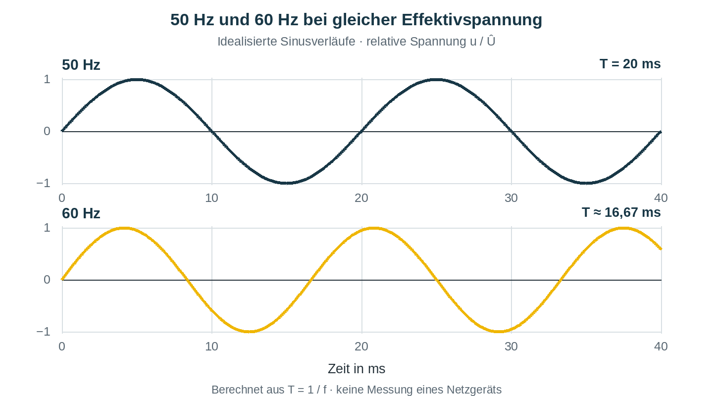
The difference between 50 and 60 Hz lies not in the voltage level, but in the duration of a cycle. At 50 Hz, it is 20 ms; at 60 Hz, it is approximately 16.67 ms. The root-mean-square voltage can be the same in both cases. The effect of this change on the device depends on its design.
What Might Change for Consumers
In an asynchronous motor operated directly from the grid, the frequency, together with the number of poles, determines the synchronous speed of the rotating field. For four poles, this results in a calculated speed of 1,500 min⁻¹ at 50 Hz and 1,800 min⁻¹ at 60 Hz. The actual rotor speed is lower than this during motor operation and depends on the load. If the motor is driving a fan, for example, it is therefore important to consider not only the current but also how the driven process changes.
With an electronic assembly, different questions arise. Does it start up reliably? Does its internal power supply remain stable? Does the temperature change under the intended load conditions? The specifications on a built-in power supply do not automatically answer these questions for the entire device. The unit under test may also include fans or transformers, whose permissible voltage and frequency combinations must be taken into account.
A designation such as “50/60 Hz” must therefore be read in conjunction with the corresponding voltage values. In this example, only explicitly approved operating points are compared. A transformer designed solely for 60 Hz would not be a suitable candidate for an untested trial at the same voltage and 50 Hz.
A specific question leads to a well-defined test procedure. For example, if you are examining the stability of an auxiliary voltage, you measure it at both frequencies under the same load condition. When dealing with a drive, speed and startup conditions may also be relevant. Such a comparison provides more insight than simply changing the frequency without a defined set of observations.
Why 115 V Can Draw More Current Than 230 V
If different rated voltages are also to be considered, the current reserve of the source becomes important. A power rating in watts alone is not sufficient for selecting an AC power supply. For a single-phase load, the apparent power is given by S = Uᵣₘₛ × Iᵣₘₛ. The power factor λ = P / S relates this to the active power P consumed.
Let’s consider a purely theoretical load that can be operated at both 230 V and 115 V. For both voltages, we’ll assume 1,200 W of active power and a power factor of 0.80. This results in:
| Size | Operates at 230 Vᵣₘₛ | Operation at 115 Vᵣₘₛ |
|---|---|---|
| Assumed active power P | 1.200 W | 1.200 W |
| Assumed power factor λ | 0,80 | 0,80 |
| Reactive power S = P / λ | 1,500 VA | 1,500 VA |
| Effective current I = S / U | approx. 6.52 A | approx. 13.04 A |
At half voltage, this assumed load requires twice the effective current. This explains why a power source can cover the 230-V point but still supply too little current at 115 V. For a real test specimen, the values are determined at the respective operating points; active power and power factor do not have to remain the same when the voltage changes.
How the two output sections of the DF-C6105 help
The DF-C6105 supplies single-phase sinusoidal AC voltage at 47 to 63 Hz. For voltages up to 150 Vᵣₘₛ L–N, the LV range is available with up to 45 A. The FS range extends up to 300 Vᵣₘₛ L–N at up to 22.5 A. In both ranges, the apparent power limit of 5 kVA also applies; voltage and current maximums cannot be combined arbitrarily.
In the calculation example, the 230 V and approximately 6.52 A fall within the FS range. For 115 V and approximately 13.04 A, the LV range can be used. Both points require 1.5 kVA each and are therefore within the model’s operating range based on the rated values. This switching capability provides a higher current limit for tests at lower voltages, rather than basing the selection solely on the highest output voltage.
Together with the separate frequency setting, this makes it possible, for example, to examine permissible 115-V and 230-V operating points at 50 and 60 Hz, respectively. Which point is appropriate and permissible for the actual test specimen depends on its design. The calculated steady-state operation alone does not indicate whether the source can also handle the startup process.
Include the run-up in the comparison
Motors, transformers, and capacitive inputs can draw significantly more current for a brief moment when powered on than during steady-state operation. If the power source reaches its limit during this process, the voltage may drop or a protective function may shut off the output. In that case, the power source affects the observed startup behavior.
Therefore, the selection of equipment must also take into account the magnitude and duration of the inrush current, as well as the voltage required during this phase. A load profile helps to coordinate these requirements with the power source. If a drive is capable of feeding energy back into the grid under certain conditions, the acceptance of this energy must also be clarified separately; the provision of an AC voltage does not in itself confirm this capability.
When making comparisons, record not only the settings but also the voltage, frequency, and load condition actually measured on the test specimen. For temperature comparisons, this includes a comparable initial thermal state. This turns two frequency settings into a verifiable functional comparison. For standard-compliant validation, the requirements of the respective test procedure regarding the source and measuring equipment must also be met.
Are you planning to set up a test station like this? Please send the permissible voltage and frequency combinations, number of phases, operating current, and any available startup data to service@dsc-electronics.de. We will help you select the right AC configuration for your test specimens.
