
A low-voltage, high-current electrolysis stack places different demands on the power supply than a high-voltage, low-current load. Both can draw the same amount of power. Therefore, the kilowatt rating alone is of little help in making a selection. The key factor is whether the power supply unit can deliver the required current throughout the entire intended operating range and provide sufficient voltage to do so.
This applies to the development of electrolyzers and electrochemical laboratory experiments as well as electrolytic surface treatment. A few questions can help you determine how to select a suitable DC power supply: How does the load vary? Should current or voltage be regulated? And what losses occur between the source and the cell?
Why the operating point shifts
In water electrolysis, electrical energy breaks down water into hydrogen and oxygen. Alkaline and PEM electrolysers differ, among other things, in their electrolytes, electrodes, and design. Their electrical characteristics depend on the technology and operating conditions. If these conditions change, a different current may flow at the same applied voltage . The U.S. Department of Energy describes the basic electrolysis technologies.
A polarization curve aids in the design process. It shows which cell or stack voltage corresponds to a specific current density. The curve is meaningful only when considered together with the measurement conditions: temperature, pressure, and flow rate must be included in the report. This allows for a meaningful comparison of experiments later on. The harmonized JRC test methodology specifies these conditions.
Cell size also plays a role. The current density j = I / A relates the current to the active area A defined for the process. The same current can place a heavy load on a small cell but a significantly lighter one on a larger cell. For this reason alone, amperes are not sufficient for comparison.
Over time, electric current carries an electric charge. For a constant current, Q = I × t; for a varying current, the value is integrated over time. The proportion of the charge that contributes to the desired chemical reaction depends on the current yield and possible side reactions. Therefore, doubling the current does not automatically guarantee twice the amount of usable product. The harmonized JRC terminology explains charge, current density, and electrochemical yield.
The power system needs a voltage reserve
If you want to send a fixed current through the cell, constant-current (CC) mode is the best option. The power supply adjusts its voltage so that the set current flows. It can only compensate for changes in cell voltage within its voltage reserve. Once it reaches the set voltage limit, it switches to voltage regulation. The current is then determined by the voltage and the connected process.
Select the limit based on the permissible process values. The maximum available power supply voltage is not a permissible operating value for every stack. However, if an experiment is to follow a specified voltage curve, CV (constant voltage mode) may be the appropriate control mode. The test or process plan determines which variable is controlled and which is limited.
In a stack of cells connected in series, the cell voltages add up, while the same current flows through all the cells. If a system contains multiple stacks, their interconnections must also be taken into account. The JRC test reports describe the design and operating conditions of cells and stacks.
Also take into account voltage drops across wires, contacts, and other components. The entire intended operating range is decisive, including the highest cell voltages under permissible operating conditions. A power supply that meets the requirements at the warm-run rating may already reach its voltage limit at another point. Each required point must comply with the device’s voltage, current, and power limits, as well as its permissible continuous load.
Calculation Example: What Gets Lost Between the Source and the Stack
For a purely illustrative electrical example, let’s assume ten cells connected in series. At the operating point under consideration, each cell requires 2.0 V at 60 A. These values are not specifications for a real electrolysis process. We assume a resistance of 10 mΩ for the entire supply and return lines:
| Size | Calculation | Result |
|---|---|---|
| Voltage at the stack | 10 × 2.0 V | 20,0 V |
| Electrical Power at the Stack | 20.0 V × 60 A | 1.200 W |
| Voltage drop across the entire forward and return lines, assuming 10 mΩ | 60 A × 0.010 Ω | 0,6 V |
| Power loss in this loop | 60² A² × 0.010 Ω | 36 W |
| Required starting point of the source without further losses | 20.0 V + 0.6 V at 60 A | 20.6 V / 1,236 W |
The stack uses 1,200 W, and the cable loop converts an additional 36 W into heat. To achieve this, the source must deliver 1,236 W. Its power consumption is higher by the amount of its own losses. The additional voltage component compensates for the line loss but does not prevent the lines from heating up.
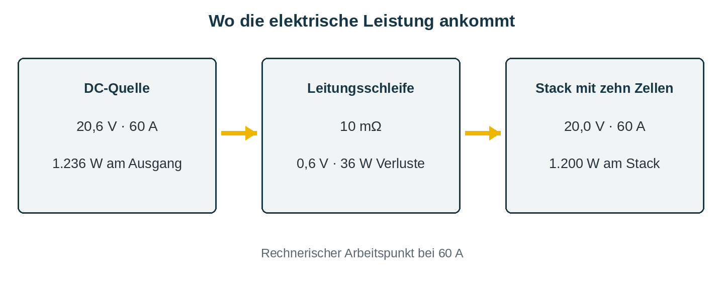
This example also illustrates why the measurement location matters: A voltage measurement taken directly at the power supply terminals measures the voltage at the device. For the process, you are interested in the voltage at the stack. With suitable devices and operating modes, Remote Sense can base the voltage regulation on this load connection. The respective operating instructions specify when and how this is permitted. Proper sizing of the power cables and process measurement remain necessary.
How smoothly does the current need to flow?
Residual ripple—unwanted fluctuations around the DC component—also affects current quality. Therefore, when comparing data sheet values, be sure to consider the amplitude, frequency range, and measurement conditions. Peak-to-peak and RMS values cannot be directly converted into one another without knowing the signal waveform.
Current quality can be a factor for electrolysers. Parache and co-authors investigated superimposed current ripple in a 3,000-hour test on PEM electrolysers. Certain waveforms examined influenced aging. The results also demonstrate how important the system and waveform are for the assessment. This does not allow for the derivation of a general threshold value for every electrolyzer, nor does it promise a higher yield based solely on a small data sheet value.
For procurement, specify the current quality required by the process at its operating points. This includes the planned partial-load range. The supplier should be able to explain the conditions under which its specifications apply.
What the test procedure requires of the power supply unit
In development tests, currents are often adjusted incrementally while voltage, temperature, and time are recorded. To ensure that the process is repeatable, the setpoint curve, measurement times, and process conditions must align. Therefore, the interface must also address how quickly the output responds to a new setpoint at the actual load.
If you plan to use fast pulses or polarity changes, be sure to specifically verify the required output stage, edge characteristics, load response, and permissible back-energy. A programmable DC power supply does not automatically have these capabilities. How such operation affects the electrochemical process is a separate research question.
Cover the sample point with the DP-P series
The DP30-80P, with a rated output of 30 V, 80 A, and 2.4 kW, meets the calculated requirements of 20.6 V and 60 A—equivalent to 1,236 W—based on its rated specifications. It offers CC/CV control as well as RS232 and RS485 with Modbus RTU. This allows an external test controller to set setpoints and query actual values. Optionally, LAN and an independent analog I/O package can be added to the connectivity. The analog package replaces an existing RS232 connection.
When selecting a real-world configuration, factors such as the remaining operating points, the required control quality, the process limits, and the behavior upon shutdown must also be considered. Larger systems also require an appropriate device configuration: This 2.4-kW model does not support Master/slave parallel operation. This feature of the DP-P series is reserved for the 15-kW modules designed for that purpose.
This information will help you make your selection
In an electrolysis plant, the power supply works in conjunction with the rest of the process control system. Temperature, media supply, gas flow, and pressure can limit permissible operating conditions. The plant control system must be able to respond to these factors. An interlock on the power supply unit can be integrated into this concept, but it alone does not constitute a complete safety device for the chemical process.
For the technical pre-selection, please describe your cell or stack configuration, voltage and current ranges, continuous operation, and load profile. It is also helpful to provide the desired measurement and connection specifications, as well as the process’s limit and shutdown conditions. Please send this key information to service@dsc-electronics.de. We will assist you in tailoring the output range and equipment to your test setup.
